ResMed Adapt SV vs. Respironics Auto SV

General Discussion on any topic relating to CPAP and/or Sleep Apnea.
-SWS
Posts: 5301
Joined: Tue Jan 11, 2005 7:06 pm

Post by -SWS » Mon Mar 24, 2008 8:04 am

SAG wrote:I don't know what that would do. However, for a moment, let's say what SAG said about K1 - K2 is true, that it analyzes activity on a flow wave, and that identifying the integral as "+" or "-" simply defines a segment of the wave. So instead, solving for a point instead of the integral, we're left with Pdelta = K1(Flow)^2 + K2(Flow). The flow in K1 must be squared because in turbulent flow, in order to end up with the same pressure result, the driving pressure needs to be squared. While the K1 - K2 concept considers the phenomena of laminar and turbulent flows in its understanding, it is calculated in terms of resistance, or P/Flow = K1(Flow) + K2.
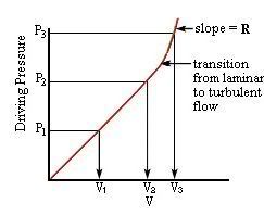
In the original equation of "sum of turbulent plus laminar flows" that squaring turbulent portion was originally derived in that manner to mathematically describe turbulent flow's sum total effect over time toward calculating total flow. Right? That type of end-result or final-equation squaring technique is employed in many steady state equations, especially, to account for very minute "up-and-down" contributions as they are more gradually spread throughout time.

Contrary to that time-averaging type of calculation, I'm talking about using instantaneous values to decompose circuit-characteristic transitional flow in fluid dynamics, toward table-based circuit identification. What I had in mind was launching turbulent pulse waves in the time domain to:

1) isolate/decompose turbulent and laminar ratio-based component values, based on multiple characteristic discrete point returns

2) specifically use fluid dynamics calculations to arrive at two highly unique sets of discrete decomposed values for turbulent and laminar components (one discrete paired identifier set before pulse launch and another discrete identifier pair after wave-reflection returns, using multiple unique-return pulse or step functions),

3) table-map those multiple discrete paired identifier sets into characteristic function-mapping table entries (not yet the K1 and K2 equation where final squaring occurs)

4) use the returned characteristic table-mapping to return from your "empirically determined" table of circuit-identifying functions, thus returning with K1 and K2 values

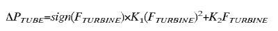
5) With those now-identified K1 and K2 values, use flow measurements to plug into the equation below (now squaring that K1 portion), to arrive at pressure loss on the left:
Image

So I wouldn't even propose doing what you have suggested above. What I had in mind is a completely different technique taking advantage of instantaneous values in the time domain (to decompose values for turbulent flow and laminar flow toward table-based circuit identification). And toward instantaneous point-mapping of decomposed values, then an Ohm's-based P/Flow = K1(Flow) + K2 becomes a very practical circuit-identifying equation toward this type of discrete point-based table mapping (the negative turbulence-resistance wisecrack yields a "dirty math trick" chuckle and thus the basis for "running for cover").

Enough said on that proposed algorithmic technique. Resmed may be reflecting waves during Learn Circuit, but I now strongly doubt they're performing a decomposition technique similar to what I have described above. On the notion of wave-reflection even a lowly 0.5 cm FOT is wave-reflection capable. That's why I was wondering about the exact nature of Learn Circuit's pressure output functions.

Regardless, I suspect Resmed may even be able to get by with more basic (unreflected) flow measurements and one-to-one mapping against their "empirically derived" table values for their no-proximal-sensor embodiment.

The proximal-sensor embodiment clearly makes life much easier.

My point is that Resmed's no-proximal-sensor embodiment in the patent description is turbine-flow measured (only) and thus table-derived (that table creation having occurred during Resmed's R&D phase when "empirically determined" entries went into development of that reference table). And if Resmed has that no-proximal-sensor embodiment in their patent description, then they have successfully implemented it. So a compelling question, at least in my mind, is whether that technique still looms in the algorithm for fall-back or at least comparison purposes.

Speaking of looming, ennui of the arcane understandably looms... including here. Me thinks it's time to pack it in. Thanks!


User avatar
StillAnotherGuest
Posts: 1005
Joined: Sun Sep 24, 2006 6:43 pm

I'm Back From the Winn-Dixie!

Post by StillAnotherGuest » Mon Mar 24, 2008 8:36 pm

-SWS wrote:
SAG wrote:During Learn Circuit, a series of steady flows, lasting about 3 seconds each and increasing in step-wise fashion, is delivered through the circuit.
Also wondering what happens on the leading edge of those 3 second wave functions? Sharp or gradual increase? Is the 3 second flow test of a fixed magnitude (zero slope)? Also wondering what happens after that 3 second period? Sharp or gradual drop to baseline? Or a progression up to the next flow-magnitude of a staircase function? If a drop to baseline is it a zero-flow or non-zero flow baseline?
The series of pressures ranges from about 1.0 - 6.0 cmH2O as measured at the machine. This results in pressures ranging from about 0.2 - 1.2 cmH2O at the proximal end. The duration of each step becomes shorter as the sequence progresses. The transition to each step is not smooth, with a pressure spike at the beginning of each step. This is seen clearly on the machine end, much less so at the proximal end. The pressure during the remainder of the step appears stable. Flow was not measured.

SAG
Image

Aromatherapy may help CPAP compliance. Lavender, Mandarin, Chamomile, and Sweet Marjoram aid in relaxation and sleep. Nature's Gift has these and a blend of all four called SleepEase.

Lubman
Posts: 121
Joined: Sat Apr 29, 2006 10:10 am

Interesting, but too tired to really concentrate

Post by Lubman » Mon Mar 24, 2008 8:45 pm

So my disappearance will not be thru lack of interest
To paraphrase DSM, I find this interesting and if I wasn't so damn tired
I could actually concentrate and follow the details.

I have occasionally wondered if the Learn Circuit had any parallels to measuring a Radio Frequency circuity with a time domain reflectometer.

But - this topic may be considered arcane, but don't stop on our account.
It's good stuff.

I believe it is hard to disagree with the fact that the ResMed Assist SV is an elegant design solution.

Lubman

I'm not a medical professional - this is from my own experience.
Machine: ResMed Adapt ASV with EERS
Mask: Mirage NV FF Mask
Humidifier: F&P HC 150
Sleepzone Heated Hose

User avatar
StillAnotherGuest
Posts: 1005
Joined: Sun Sep 24, 2006 6:43 pm

Is the State of Arcane Called Arcansas?

Post by StillAnotherGuest » Tue Mar 25, 2008 3:22 am

-SWS wrote:Take everything apart, throw in a blender, reassemble, etc.
-SWS wrote:Resmed may be reflecting waves during Learn Circuit, but I now strongly doubt they're performing a decomposition technique similar to what I have described above. On the notion of wave-reflection even a lowly 0.5 cm FOT is wave-reflection capable. That's why I was wondering about the exact nature of Learn Circuit's pressure output functions.
Well, speaking "empirically", I would think that if ResMed was using that sort of technology, the marketeers would have picked up on it:

Simply Amazing! And it FOTs, too!

And if that were the case, one would think that some mention of it would have to be in the patent, or the patent for whatever "pulse-wave" technology is in there would be on the AdaptSV patent list (if somebody feels ambitious).

However, MBJ has been known to fiddle with FOT, and I suppose stranger things have happened. My analysis of the pressure in Learned Circuit was done somewhat grossly. A little amplification of the signal should reveal a FOT, but on the other hand, I would think that FOT, or any other "pulse wave technology", becomes less accurate in the face of leaks. Learn Circuit is just one big leak and nothing gets reflected. If you had FOT capability you'd be using it for other stuff, like apnea identification and not just circuit properties. Further, if you use "pulse wave technology" and somehow solve for resistance, then you don't need K1 - K2, you're done. You really don't care about what the K1/K2 proportion is, you're just trying to get to Pmask when you're not physically measuring Pmask.

"Fiddle with FOT."

SAG thinks that's funny.

SAG
Image

Aromatherapy may help CPAP compliance. Lavender, Mandarin, Chamomile, and Sweet Marjoram aid in relaxation and sleep. Nature's Gift has these and a blend of all four called SleepEase.

-SWS
Posts: 5301
Joined: Tue Jan 11, 2005 7:06 pm

Re: I'm Back From the Winn-Dixie!

Post by -SWS » Tue Mar 25, 2008 10:43 am

StillAnotherGuest wrote: The series of pressures ranges from about 1.0 - 6.0 cmH2O as measured at the machine. This results in pressures ranging from about 0.2 - 1.2 cmH2O at the proximal end. The duration of each step becomes shorter as the sequence progresses. The transition to each step is not smooth, with a pressure spike at the beginning of each step. This is seen clearly on the machine end, much less so at the proximal end. The pressure during the remainder of the step appears stable. Flow was not measured.
Thanks, SAG. The pressure spike is very interesting to me. The reason I find it interesting is because a pressure spike contains energy-wave frequency harmonics that are practically off the map. They transmit energy from all those frequency harmonics in both the forward and backward directions (even into the impeller).

So generally speaking, if a designer doesn't have a compelling reason to launch a pressure spike at the beginning of each step on that staircase function (which is what I think you've just described), then the designer wisely avoids transmitting all those energy harmonics to the impeller drive shaft. Unnecessary backward-transmitted sharp spikes cause premature wear, because of sympathetic-frequency related mechanical stress. So a designer wouldn't use them unless they had a fairly good reason. That's just standard engineering best practice. These energy-laden spikes are understandably not used in therapy for obvious reasons. And they are definitely not needed to run proximal-sensor-based Ohm's calculations (even for an open-mask configuration). And yet Resmed took extra design steps to place them in the Learn Circuit's pressure output functions.

So the energy spikes are there on the front end of each step, and Resmed undoubtedly placed them there during Learn Circuit for a compelling reason. They could have very easily achieved a much smoother and more "motor-friendly" Ohm's-measurable curve (followed by each sustained zero-slope plateau) without heavy-handed use of energy-laden harmonics in those pressure spikes. Resmed obviously needs those pressure spikes to accomplish something they consider useful. At least Resmed uses them sparingly and during Learn Circuit only. Still sound design judgment by my standards.

So the compelling question is why might Resmed have placed those wave-reflection friendly spikes at the front of each Learn Circuit pressure-step, if not for the purpose of measuring energy-wave reflection?
SAG wrote:Learn Circuit is just one big leak and nothing gets reflected.
I disagree with that one. Place a spike at the front of each pressure step, and you achieve two highly transient but entirely measurable return-effects toward unique circuit profiling: 1) a unique kinetic dispersion pattern (that can be readily sampled in the time domain for patterns or signatures, then fuzzy-resolved toward circuit identification via discrete point-mapping procedures), and 2) a unique return of harmonic frequency signatures (that might also be signature-resolved toward that same type of fuzzy-oriented circuit-identification routine).

So Learn Circuit launches reflection-friendly energy waves (spikes). And presumably the Learn Circuit routine then samples unique energy-signature returns. The uniquely returned sample-point patterns are then used toward probability-driven fuzzy-based circuit recognition (or "circuit learning").

Speaking of probability-based fuzzy-logic decisions toward basic pattern recognition: that's also what happens when the ASV employs probability-based fuzzy decisions toward understanding which central dysregulation variant they are trying to treat. The ASV needs to know which centrally-dysregulated breathing pattern they are correcting. Specifically the PAV algorithm must know how much or how little F adjustment (machine frequency) needs to occur based on fuzzy-based simple pattern recognition. That adjustment of machine frequency is how a central patient's respiration rate is corrected/treated by the ASV. If the pattern-based variant recognition somehow doesn't work, then an off-the-shelf back-up rate of 15 is progressively employed.
SAG wrote:Learn Circuit is just one big leak and nothing gets reflected.
Well, as you might have guessed from my comments above, I disagree with that statement wholeheartedly. I may do a near-future post about wave reflection, kinetic dispersion, and how those two might easily factor in the time and frequency domains toward potentially useful Learn Circuit measurements (by the way of indirectly signature-profile matching toward the correct K1/K2 combination).
SAG wrote:If you had FOT capability you'd be using it for other stuff, like apnea identification and not just circuit properties.
With such a high-conductance test circuit, the Learn Circuit routine obviously cannot use 0.4 cm FOT. Learn Circuit is transmitting heavy energy-laden pulses toward circuit identification only. For obvious reasons those heavy energy spikes cannot be used during treatment.
SAG wrote:Further, if you use "pulse wave technology" and somehow solve for resistance, then you don't need K1 - K2, you're done.
Well, no. The details are in how you "somehow solve". And the "no-proximal-sensor" embodiment entails comparison against unique combinations of paired K1/K2 values as they are represented in signature functions. Learn Circuit employs unique-pattern energy signature samples on the return of wave reflection toward pattern-matching against those unique K1/K2 "signature function profiles" in their reference table.

Presumably, once they have fuzzy-mapped discrete samples to determine which "signature function profiles" they have matched against, they return from that function-mapping routine with the correct unique K1/K2 combination. They can optionally make additional K1/K2 fine tuning judgments via yet other probability-based fuzzy routines, either during Learn Circuit or even in-session (including a variety of viable ways to algorithmically factor for humidifier water depletion).

Anyway, once Resmed comes away from their table with the correct K1/K2 combination (having "Learned the Circuit"), they can easily solve for pressure loss via this particular patent embodiment by taking advantage of those kinetically characteristic turbine flow measurements acquired during Learn Circuit. Now that Learn Circuit has already fuzzy-mapped the correct K1/K2 based profile, the ASV knows how to calculate circuit-pressure loss on the fly thereafter (with more fuzzy-based decisions relative to kinetic dispersion likelihoods, associated with ongoing turbine flow measurements throughout the night).

In other words, because this embodiment can only measure turbine flow, it must algorithmically maintain (kinetic ratio) turbulent/laminar fuzzy-based likelihoods throughout the entire sleep session. K1/K2 values are thus retained throughout the entire night toward those ongoing fuzzy-based pressure loss calculations (which can only be based on flow-measurements and probability-determined K1/K2 flow-ratios with this particular embodiment). But again, that would only be Resmed's "no-proximal-sensor" embodiment we are discussing. And it sounds to me as if that embodiment is still kicking around in the ASV algorithm (based on highly methodical pressure spiking during Learn Circuit).

Regardless, the alternative or complementary proximal-sensor embodiment sure makes life much easier from my point of view as well.

Not to sound pushy, but what's the status on my Oreo cookies from Winn-Dixie? I rely on those as part of my evening sleep-therapy regimen.

Lubman wrote:I believe it is hard to disagree with the fact that the ResMed Assist SV is an elegant design solution.
I most definitely agree with you there, Lubman! I personally respect the ASV design accomplishment immensely. But I also respect great designs from some of the other CPAP companies as well---not to play company favorites on this board of all places!


User avatar
StillAnotherGuest
Posts: 1005
Joined: Sun Sep 24, 2006 6:43 pm

Where's The Beef?

Post by StillAnotherGuest » Wed Mar 26, 2008 4:40 am

-SWS wrote:
SAG wrote:Further, if you use "pulse wave technology" and somehow solve for resistance, then you don't need K1 - K2, you're done.
Well, no. The details are in how you "somehow solve". And the "no-proximal-sensor" embodiment entails comparison against unique combinations of paired K1/K2 values as they are represented in signature functions. Learn Circuit employs unique-pattern energy signature samples on the return of wave reflection toward pattern-matching against those unique K1/K2 "signature function profiles" in their reference table.
Very clearly I demonstrated that when a high resistance state is created that causes Learn Circuit to fail, it can be made to pass when Pprox = 0. There's no reflective anything. When you hear hoofbeats, don't think zebras.
-SWS wrote:I may do a near-future post about wave reflection, kinetic dispersion, and how those two might easily factor in the time and frequency domains toward potentially useful Learn Circuit measurements (by the way of indirectly signature-profile matching toward the correct K1/K2 combination).
Here. I'll start it for you...

"Once upon a time..."

What evidence in the Medical Literature is there that this technology that you're proposing actually exists in AdaptSV? Or at all? (Limit the search to "Medical Literature" so there isn't an endless list of references to "Popular Mechanics" or "The National Enquirer".)

What is the amplitude and frequency of the pulse generation you're proposing? Given that, tell me how you can't avoid solving for resistance and making K1 - K2 absolutely unnecessary.
-SWS wrote:
SAG wrote:If you had FOT capability you'd be using it for other stuff, like apnea identification and not just circuit properties.
With such a high-conductance test circuit, the Learn Circuit routine obviously cannot use 0.4 cm FOT. Learn Circuit is transmitting heavy energy-laden pulses toward circuit identification only. For obvious reasons those heavy energy spikes cannot be used during treatment.
Oh really? I didn't think they looked all that bad. Besides, just because you have FOT or some other pulse-generating technology doesn't mean you have to crank it up full-blast with the "Bass Boost" on all the time.
-SWS wrote:Speaking of probability-based fuzzy-logic decisions toward basic pattern recognition: that's also what happens when the ASV employs probability-based fuzzy decisions toward understanding which central dysregulation variant they are trying to treat. The ASV needs to know which centrally-dysregulated breathing pattern they are correcting. Specifically the PAV algorithm must know how much or how little F adjustment (machine frequency) needs to occur based on fuzzy-based simple pattern recognition. That adjustment of machine frequency is how a central patient's respiration rate is corrected/treated by the ASV. If the pattern-based variant recognition somehow doesn't work, then an off-the-shelf back-up rate of 15 is progressively employed.
Fiddle-FOT.

Gad, that still cracks me up.

SAG
Image

Aromatherapy may help CPAP compliance. Lavender, Mandarin, Chamomile, and Sweet Marjoram aid in relaxation and sleep. Nature's Gift has these and a blend of all four called SleepEase.

-SWS
Posts: 5301
Joined: Tue Jan 11, 2005 7:06 pm

Equation Doesn't Work Without Kinetic Ratios

Post by -SWS » Wed Mar 26, 2008 8:55 am

SAG wrote:What is the amplitude and frequency of the pulse generation you're proposing? Given that, tell me how you can't avoid solving for resistance and making K1 - K2 absolutely unnecessary.
Resmed's Flow-Based Equation Doesn't Work Without Continuously Maintaining Transient Kinetic Ratios For The Following Disclosed Embodiment (K1/K2 kinetic constants required):

Do you recall Resmed's disclosed purpose for this equation?
Image
That's Resmed's equation from Resmed's patent description disclosure. They might have worked with pressure measurements at the machine, but Resmed tells us they will solve pressure loss across the tube as a function of measured turbine flow instead.

Specifically, Resmed is telling us that with only flow measurements at the turbine (for this disclosed embodiment), all they have to work with toward continuously solving for pressure on the left side of the equation throughout the entire night are these two additional things (in addition to ongoing turbine-flow measurements):

1) K1 and K2, and

2) a completely indispensable turbulent/laminar fuzzy-based ratio
(so at any given fuzzy-discrete flow-measurement moment, how else are you going to continuously solve Resmed's equation without an ongoing kinetic approximation of what happens to be turbulent (flow-squared) and what happens to be laminar (not flow-squared)? Remember that this Resmed embodiment is stuck working with nothing but turbine-flow measurements.)

Right, so this successfully implemented Resmed embodiment (not Resmed's other working embodiment) has only machine-end flow measurements to work with toward solving pressure. When you're stuck with solving pressure loss purely as a function of turbine flow, then you must continuously drag along an instantaneous fuzzy-based assessment of what that ever-so-crucial transient turbulent-to-laminar flow ratio must be (based on already-learned transient kinetic characteristics of the circuit during Learn Circuit). Resmed wants the instantaneous mask pressure calculations, and not steady state calculations SAG has in mind.

The reason you must continuously drag both K1-and-K2 along with turbulent-to-laminar ratios (using this Resmed-disclosed embodiment and equation) can be summed up as knowing how much measured turbine flow to square, and how much of that same measured turbine flow not to square during kinetic-based flow addition. Hey, it's Resmed's embodiment and Resmed's equation disclosure. Not mine. But as a functional and patent-protected embodiment it requires that the ASV machine learn transient kinetic-based circuit characteristics during Learn Circuit. Otherwise Resmed would not have been able to get it working in order to protect it as a mathematically viable embodiment in their patent description.

Toward solving this Resmed patent description embodiment only: How else is Resmed going to continuously drag along those ever-so equation-crucial kinetic turbulent/laminar ratios without already having learned the kinetic characteristics of the circuit during "Learn Circuit"?

Simply amazing that Resmed has the audacity to do some very subtle things in transient kinetic physics and fuzzy-based recognition during Learn Circuit that SAG has never heard of. It's reminiscent of suggesting that all central-dysregulation pathogenesis research really needs to be confined to SAG's favorite "functionally flat" control-system model in contemporary RT text books.

SAG, please don't feel offended when I tell you that I am so done going round-and-round with you on this topic. Please continue maintaining whatever views you think are correct. That's one of the sheer beauties of individualism. Isn't it?


User avatar
StillAnotherGuest
Posts: 1005
Joined: Sun Sep 24, 2006 6:43 pm

It Ain't ResMed's Equation

Post by StillAnotherGuest » Thu Mar 27, 2008 3:43 am

Well fine there, Mr. Huffy! At least the Bose 601 Pulse Generator is gone.

Learn Circuit would seem to represent a fine example of the application of the K1 - K2 principle (and I say "seem" because K1 - K2 was presented as an alternative if Pmask wasn't measured directly).

In K1 - K2 (which, for us "functionally flat" thinkers with our contemporary RT text books is referred to as the Rohrer Equation), a low flow, which is presumed to be all laminar in nature, is transmitted through the circuit. The P1 - P2 gradient is divided by flow to give a baseline value (K1). A series of increased flows are then sent through the circuit and plotted on an xy axis. If the circuit is filled with paraphernalia like bacterial filters, humidifiers, nasal pillows and Bret's whatever the heck that was, small increases in flow will result in large increases in pressure. The resultant curve will be steep (the K2 coefficient will be large). This phenomenon is illustrated in the graphic link posted previously:

Image

In creating a Rohrer graph, Driving Pressure would be replaced by Resistance (P/V). In plotting P/V against V, a purely laminar flow would then be flat, or the distance between 0 and V3, and K1 = 0.

If AdaptSV was, in fact, using FOT, one would ask if the proximal line was even necessary. In the only semi-readily available machine using FOT (Somnosmart2), you can see very clearly that

Image

OK, maybe that's not a good example.

SAG
Image

Aromatherapy may help CPAP compliance. Lavender, Mandarin, Chamomile, and Sweet Marjoram aid in relaxation and sleep. Nature's Gift has these and a blend of all four called SleepEase.

-SWS
Posts: 5301
Joined: Tue Jan 11, 2005 7:06 pm

I Caught a FOT Thought!

Post by -SWS » Thu Mar 27, 2008 10:06 am

I leave you with one last observation about FOT in relation to leaks:

Life is one big leak into the afterlife... So we might as well take some enjoyable time to FOT around a bit before that profound leak is done!

Take care!

-SWS
Posts: 5301
Joined: Tue Jan 11, 2005 7:06 pm

Resmed Managed to Get It Working

Post by -SWS » Fri Mar 28, 2008 11:42 am

StillAnotherGuest wrote:Learn Circuit would seem to represent a fine example of the application of the K1 - K2 principle (and I say "seem" because K1 - K2 was presented as an alternative if Pmask wasn't measured directly).
I'm thinking the "no-proximal-sensor" implementation is still kicking around in there---as either a legacy fall-back (toward fault tolerance) or as a complementary embodiment (perhaps even toward "sanity" validation of the Pmask measurement method). Or perhaps even toward serving both of those auxiliary objectives. I suspect the K1/K2 flow-based method was likely a legacy prototype embodiment---before the proximal sensor ever made its way into the ASV's evolutionary design phases.

If so, then those Learn Circuit pressure plateaus (presumably for measuring purely laminar flow) and those preceding pressure spikes (presumably for measuring turbulent-injected mixed flow) are, as you say, fine examples of a viable method to "learn" K1 and K2.

While the clearly superior Pmask proximal-measurement method is definitely in there, I question whether it really needs a Learn Circuit procedure, though--even if it opportunistically participates during Learn Circuit. Either way, I suspect most of us are in agreement that it is much better to measure instantaneous pressure at the mask (Pmask) than to remotely calculate via approximated or even "learned" kinetic flow ratios.


(abscessed tooth impacting trigeminal neuralgia: my humble apologies for any perceived huff)