


DSM - thanks, I will bookmark it now. I would love to have one for a backup since Repironics doesn't seem too excited about getting a replacement here.
In fairness to Repironics, my unit is still working "ok", just the strange noises make me uncomfortable.
Great discussion. I need to go through and find the links to see what we have.
ResMed Adapt SV vs. Respironics Auto SV
How Do You Satisy Dual-Direction K1 Equations, Then?
SAG, I think we'll have to simply disagree on the hows and why Pressure delta is derived without a proximal sensor line in that patent description.
The essence of my explanation above can be summed up as the following four points in bold:
1) That P delta equation was derived early in the design phase, before there was ever a proximal sensor line (did you notice the patent description shows fewer sinusoidal reference points that are entirely consistent with no-proximal-sensor sampling, while the marketing literature shows more peak sinusoidal reference points that can only be sampled with a proximal sensor line?)
2) Without a proximal sensor line: fluid dynamics, time-domain wave reflection, and a working (albeit highly practical) dynamic-resistance model very nicely solve a close fuzzy-based table approximation for K1 and K2 (during that initial wave reflection, cohesive laminar flow briefly tends to exit around the edges of the mask, as turbulent flow briefly reflects back to the turbine flow sensor, where it can be nicely measured and subsequently table-compared---easily within today's sampling rate time windows). Repeatedly measure flow, then fuzzy table-solve for both K1 and K2, and you thus may now very nicely calculate delta P. How many approved/allowable combinations of hose, mask, humidifier are there? That's a very easy "empirically derived" (to quote from the patent) fuzzy table to build and then K1/K2 match against---especially when your time-domain reflection yields not one but two corroborative equations toward your fuzzy-based mapping.
Regardless of where baseline flow is (zero baseline or larger) during post-wave reflection-based flow data procurements, those dual Resistance equations easily fuzzy-map both K values toward a delta P calculation (since we're continuously measuring Flow at the turbine). Does the flow ever suddenly and intentionally stop during Learn Circuit? If so then I'll have to stick with a zero-flow-baseline wave-reflection guess, SAG. If not, then I think turbulent-flow baseline subtraction becomes a better contributing candidate (albeit still via an intentional wave-reflection superimposition on that flow baseline in order to yield a dual-opposed transient fluid dynamics relationship between laminar and turbulent flows). How else are you going to make that measurement-convenient relationship happen in physics, SAG? Reverse-flow eddies don't fit sampling rate time windows (and about are as non-deterministic as individual particle travel happens to be in quantum physics).
3) Once a proximal sensor line finally makes it into the ASV's evolutionary design phase, then it makes very good sense to use that proximal sensor (hence both techniques are clearly represented in the patent description).
4) If you do have both algorithmic techniques available, then the early technique set is still available for both fall-back scenarios and validation of the new technique. (please take a peek at my speculation in the paragraph immediately below)
On the subject of keeping the old (pre-proximal) algorithmic techniques handy for fault-related fall-back. When you jammed the proximal sensor and noticed only slight system-output skew, then you probably observed the old algorithmic techniques taking over as a viable fall-back algorithm (to compensate for your intentionally disabled sensor line). Banned probably noticed the same old-algorithm (pre-proximal-sensor) fall-back measures during his similar proximal-sensor-jamming experiment as well.
Did I mention what an arcane thread this has become?
Learn Circuit: Any Sharp Pressure Ramping?
SAG, I agree that if you have a proximal sensor line it makes great sense to simply measure and use an integral method. I just thought of a very cool way to better guess at just what Learn Circuit might be up to.
Specifically, if we can characterize the Learn Circuit's pressure output into one of these three wave-function categories, then we can better guess (uh oh, I just now did the group-think thingy):
1) Exclusively smooth and semi-smooth system-output pressure functions- then there are no time-domain wave reflection measurements occurring (only proximal sensor integrals).
2) Mainly sharp and sudden pulses- then pressure wave reflection is clearly employed, to set up that measurement-convenient dual-direction relationship between laminar and turbulent flow vectors (and you need to be back at the turbine sensor to pick off wave reflection; also, it "small-table fuzzy-maps" as a highly characteristic series of discrete measurements exceptionally well---and discrete point-mapping is precisely what makes a highly-practical dynamic-resistance math model viable IMO)
3) Some combination of the above two- In which case Resmed is probably intermixing both techniques.
Banned, how might you characterize the pressure functions sourced on the output side by Learn Circuit? One, two, or three above?
Interesting as all get-go from my perspective...
Re: Learn Circuit: Any Sharp Pressure Ramping?
That would be two (2). It definitely pulses at a fixed rate, starting from a very low velocity and steadily increasing (and notably louder) velocities until (probably) MAX PS is reached-SWS wrote: 1) Exclusively smooth and semi-smooth system-output pressure functions- then there are no time-domain wave reflection measurements occurring (only proximal sensor integrals).
2) Mainly sharp and sudden pulses- then pressure wave reflection is clearly employed, to set up that measurement-convenient dual-direction relationship between laminar and turbulent flow vectors (and you need to be back at the turbine sensor to pick off wave reflection; also, it "small-table fuzzy-maps" as a highly characteristic series of discrete measurements exceptionally well---and discrete point-mapping is precisely what makes a highly-practical dynamic-resistance math model viable IMO)
3) Some combination of the above two- In which case Resmed is probably intermixing both techniques.
Banned, how might you characterize the pressure functions sourced on the output side by Learn Circuit? One, two, or three above?
Banned
AVAPS: PC AVAPS, EPAP 15, IPAP Min 19, IPAP Max 25, Vt 520ml, BPM 10, Ti 1.8sec, RT 2 (Garage)
BiPAP Auto SV: EPAP 9, IPAP Min 14, IPAP Max 25, BPM 10, Ti 2sec, RT 2 (Travel Machine)
VPAP Adapt SV: EEP 10.4, Min PS 4.4 (Every Day)
Mask: Quattro
BiPAP Auto SV: EPAP 9, IPAP Min 14, IPAP Max 25, BPM 10, Ti 2sec, RT 2 (Travel Machine)
VPAP Adapt SV: EEP 10.4, Min PS 4.4 (Every Day)
Mask: Quattro
On careful reflection, I think there's plenty of time-domain wave reflection going on here (as long as the answer is either 2 or 3).
And you can take that highly practical dynamic-resistance model to the bank IMHO. Measure turbine flow, small-table fuzzy-solve for both K constants (using the dynamic resistance model), and you know exactly what delta P is.
Thanks, Banned! .
And you can take that highly practical dynamic-resistance model to the bank IMHO. Measure turbine flow, small-table fuzzy-solve for both K constants (using the dynamic resistance model), and you know exactly what delta P is.
Thanks, Banned! .
So would Learn Circuit on the Adapt SV be necessarily any smarter or better then the method employed on the BiPAP Auto SV (whatever method that is, or isn't)?
Banned
Banned
AVAPS: PC AVAPS, EPAP 15, IPAP Min 19, IPAP Max 25, Vt 520ml, BPM 10, Ti 1.8sec, RT 2 (Garage)
BiPAP Auto SV: EPAP 9, IPAP Min 14, IPAP Max 25, BPM 10, Ti 2sec, RT 2 (Travel Machine)
VPAP Adapt SV: EEP 10.4, Min PS 4.4 (Every Day)
Mask: Quattro
BiPAP Auto SV: EPAP 9, IPAP Min 14, IPAP Max 25, BPM 10, Ti 2sec, RT 2 (Travel Machine)
VPAP Adapt SV: EEP 10.4, Min PS 4.4 (Every Day)
Mask: Quattro
Banned, Respironics works with peak flow and thus avoids Resmed's off-track vulnerabilities attributable to narrow temporal-scope output decisions. IMO any standard Pressure Loss calculation will suffice for Respironics.
I also suspect that Learn Circuit performs at least some proximal-sensor based integrals (making choice 3 a more likely answer in my best yet admittedly blind guess). However, the proximal-based integral method really shouldn't require much of Learn Circuit's time. In fact, proximal-based integral methods shouldn't really require a Learn Circuit routine. But if you're doing Learn Circuit for yet another good reason (such as time-domain wave reflection measurements), then why not also do your smooth-function proximal-based integrals during the Learn Circuit sequencing of your test-procedure set?
If sharp pulsing occurs extensively, there's no point in attempting to integrate all that wave reflection resulting from those Learn Circuit procedures. Sharp, sudden pulsing sets up serious wave reflection. And wave reflection is the drop-dead last thing you want while you're attempting typical smooth-function integral methods.
Yet wave reflection is the drop-dead first thing you want if you're attempting to set up diametrically opposed turbulent and laminar flow vectors (yet most designers would be entirely disinclined to mathematically integrate all that time-domain end-to-end signal skewing that results from those deliberate flow-disturbing test procedures).
Those pulsing test procedures very carefully disassemble laminar and turbulent flow vectors toward "Pressure Loss" calculations as follows:
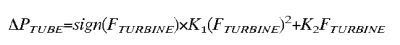
1) Measure multiple discrete sum-total flow points for both cases of turbulent flow vectors,
2) Table-map for K1 and K2 using flow measurements from both directional equations,
3) Neatly solve for "Pressure Loss" on the far left side of the equation
Case 1- Normal Flow:
Δ P TUBE = + K 1 ( F TURBINE )^ 2 +K 2 F TURBINE
(turbulent flow, in the blue K1 part of the equation, travels in the same direction as laminar flow on the far right)
Case 2- (Mathematically) Disassembled Flow:
Δ P TUBE = - K 1 ( F TURBINE )^ 2 +K 2 F TURBINE
(turbulent flow, in the blue K1 part of the equation, now opposes laminar flow on the far right)
I also suspect that Learn Circuit performs at least some proximal-sensor based integrals (making choice 3 a more likely answer in my best yet admittedly blind guess). However, the proximal-based integral method really shouldn't require much of Learn Circuit's time. In fact, proximal-based integral methods shouldn't really require a Learn Circuit routine. But if you're doing Learn Circuit for yet another good reason (such as time-domain wave reflection measurements), then why not also do your smooth-function proximal-based integrals during the Learn Circuit sequencing of your test-procedure set?
If sharp pulsing occurs extensively, there's no point in attempting to integrate all that wave reflection resulting from those Learn Circuit procedures. Sharp, sudden pulsing sets up serious wave reflection. And wave reflection is the drop-dead last thing you want while you're attempting typical smooth-function integral methods.
Yet wave reflection is the drop-dead first thing you want if you're attempting to set up diametrically opposed turbulent and laminar flow vectors (yet most designers would be entirely disinclined to mathematically integrate all that time-domain end-to-end signal skewing that results from those deliberate flow-disturbing test procedures).
Those pulsing test procedures very carefully disassemble laminar and turbulent flow vectors toward "Pressure Loss" calculations as follows:
1) Measure multiple discrete sum-total flow points for both cases of turbulent flow vectors,
2) Table-map for K1 and K2 using flow measurements from both directional equations,
3) Neatly solve for "Pressure Loss" on the far left side of the equation
Case 1- Normal Flow:
Δ P TUBE = + K 1 ( F TURBINE )^ 2 +K 2 F TURBINE
(turbulent flow, in the blue K1 part of the equation, travels in the same direction as laminar flow on the far right)
Case 2- (Mathematically) Disassembled Flow:
Δ P TUBE = - K 1 ( F TURBINE )^ 2 +K 2 F TURBINE
(turbulent flow, in the blue K1 part of the equation, now opposes laminar flow on the far right)
Last edited by -SWS on Fri Mar 28, 2008 11:22 am, edited 1 time in total.

-
StillAnotherGuest

- Posts: 1005
- Joined: Sun Sep 24, 2006 6:43 pm
On The Concept of Turbulence
Well, as the ad says, "Simply Amazing!"-SWS wrote:Those pulsing test procedures very carefully disassemble laminar and turbulent flow vectors toward "Pressure Loss" calculations as follows:
1) Measure multiple discrete sum-total flow points for both cases of turbulent flow vectors,
2) Table-map for K1 and K2 using flow measurements from both directional equations,
3) Neatly solve for "Pressure Loss" on the far left side of the equation
Case 1- Normal Flow:
Δ P TUBE = + K 1 ( F TURBINE )^ 2 +K 2 F TURBINE
(turbulent flow, in the blue K1 part of the equation, travels in the same direction as laminar flow on the far right)
Case 2- Disassembled Flow:
Δ P TUBE = - K 1 ( F TURBINE )^ 2 +K 2 F TURBINE
(turbulent flow, in the blue K1 part of the equation, now opposes laminar flow on the far right)
Given that the value of K1 is squared, how much turbulence is needed before AdaptSV turns into an Oreck XL? Even if you ran the AdaptSV though a succession of Passover humidifiers (made with unleavened plastic, and specifically designed to create a turbulent flow pattern), it won't create suction.
Mr. Reynolds wants to see you.-SWS wrote:(during that initial wave reflection, cohesive laminar flow briefly tends to exit around the edges of the mask, as turbulent flow briefly reflects back to the turbine flow sensor, where it can be nicely measured and subsequently table-compared---easily within today's sampling rate time windows).
Moving on to actual calculation of leak:
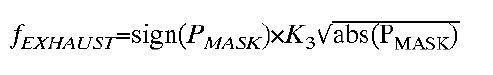
Oh-oh. There's another one of them pesky sign (x)'s, and this time there's no "sign" of a positive anything to stop the bedcovers from being sucked in.
The Concept of Negative Leak is really gonna rock the ASV World.
SAG

Aromatherapy may help CPAP compliance. Lavender, Mandarin, Chamomile, and Sweet Marjoram aid in relaxation and sleep. Nature's Gift has these and a blend of all four called SleepEase.
DSM, essentially the same principal is occurring here. LC's heavy, sharp pulsing is setting up wave reflection toward learning circuit resistance (instead of human airway resistance as in the case of FOT).dsm wrote:SWS, Is it likely it does FOT pulsing as part of LC ?
The purpose of this technique is to measure flow toward arriving at a dual-equation mapping solution for K1 and K2. Paired sets of K1 and K2 values have already been "empirically derived" as the patent description puts it. "Empirically derived" K1 and K2 values refer to these circuit-impedance related combinations already having been carefully measured in the development lab toward creation of a short reference table (for the algorithm to map against).
Turbine Flow measurements are then acquired during Learn Circuit via heavy pulsing that sets up wave reflection toward filling in both sets of equations: 1) flow measurements before each wave-reflecting pulse is launched, and 2) flow measurements after after each pulse-launched pressure wave returns it's turbulent flow vector to the turbine's flow sensor. There's absolutely no reason to perform all that heavy, sharp pulsing during Learn Circuit unless you're trying to reflect waves.
Returning measured turbine Flow values for both sets of equations (regarding turbulent flow vectors) is what makes table mapping so easy toward solving for Pressure Loss (without a proximal sensor line to directly measure pressure at the mask). As I said earlier, if you have a proximal sensor line handy to to measure pressure at the mask, then you don't even require a Learn Circuit routine.
And Resmed clearly states that running Learn Circuit serves the purpose of factoring in impedance changes so that delivered pressure at the mask is calculated correctly (after they calculate for pressure loss pending Learn Circuit's wave-reflection based dual-equation results that is). That's the purpose of Resmed's equation in my above post: to solve for resistance-related pressure losses via those paired sets of flow-measured equations.
SAG wrote:Given that the value of K1 is squared, how much turbulence is needed before AdaptSV turns into an Oreck XL? Even if you ran the AdaptSV though a succession of Passover humidifiers (made with unleavened plastic, and specifically designed to create a turbulent flow pattern), it won't create suction.
Can you please direct the entire Resmed design team to see Mr. Reynolds as well? If Learn Circuit us using heavy, sharp pulsing then Resmed is clearly setting up wave reflection toward very brief but measurable reversals of the turbulent flow vector itself.In the Learn Circuit Section of the Vpap Adapt SV User Guide, Resmed wrote:Make sure that the mask is unobstructed so that air can flow from the mask to the flow generator.
You know what they say about conclusions derived from cursory inspection? They're no substitute for measuring brief subtleties in physics using sound methodology. You can't simply hold a Kleenex up to the mask during Learn Circuit, or carefully try to vacuum the carpet for that matter, if you want to pick off this brief but extremely useful time-domain based measurement.
So what gives with those round and squishy tennis balls anyway?
Snooze Blues, I hope the data that flowed thru this thread has been helpful to your original question - a lot to follow but an immensely interesting topic.
I think we all get a bit of a buzz when exploring leading edge technologies & concepts, especially ones that directly affect our own well being.
I am off for 10 days (participating in a national classic cars rally - driving perhaps a total of 3000 miles - Sydney to Adelaide & back via the famous Barossa Valley wine growing district near Adelaide).
So my disappearance will not be thru lack of interest
DSM
Cheers all - away until 11th April.
xPAP and Quattro std mask (plus a pad-a-cheek anti-leak strap)
-
StillAnotherGuest
- Posts: 1005
- Joined: Sun Sep 24, 2006 6:43 pm
Show Me the Turbulence
This subjective assessment of the air flow characteristics of Learn Circuit is not accurate. What Banned said was-SWS wrote:Turbine Flow measurements are then acquired during Learn Circuit via heavy pulsing that sets up wave reflection toward filling in both sets of equations: 1) flow measurements before each wave-reflecting pulse is launched, and 2) flow measurements after after each pulse-launched pressure wave returns it's turbulent flow vector to the turbine's flow sensor. There's absolutely no reason to perform all that heavy, sharp pulsing during Learn Circuit unless you're trying to reflect waves.
During Learn Circuit, a series of steady flows, lasting about 3 seconds each and increasing in step-wise fashion, is delivered through the circuit. To me, they are obviously fixed, flow-oriented and come nowhere near Mr. Reynolds to talk about turbulent flow. It looks like a simple measurement of resistance via Ohm. I can objectively measure these flowrates when I return from the Wynn-Dixie with a new box of Kleenex.Banned wrote:It definitely pulses at a fixed rate, starting from a very low velocity and steadily increasing (and notably louder) velocities until (probably) MAX PS is reached
SAG
Aromatherapy may help CPAP compliance. Lavender, Mandarin, Chamomile, and Sweet Marjoram aid in relaxation and sleep. Nature's Gift has these and a blend of all four called SleepEase.
Any impeller blade reverses, SAG?In the Learn Circuit Section of the Vpap Adapt SV User Guide, Resmed wrote:Make sure that the mask is unobstructed so that air can flow from the mask to the flow generator.
Also wondering what happens on the leading edge of those 3 second wave functions? Sharp or gradual increase? Is the 3 second flow test of a fixed magnitude (zero slope)? Also wondering what happens after that 3 second period? Sharp or gradual drop to baseline? Or a progression up to the next flow-magnitude of a staircase function? If a drop to baseline is it a zero-flow or non-zero flow baseline?SAG wrote:During Learn Circuit, a series of steady flows, lasting about 3 seconds each and increasing in step-wise fashion, is delivered through the circuit.
Sorry to pester...
P.S. As long as I have your ear, would you mind picking me up a box of Oreo cookies down at that Wynn-Dixie? Thanks in advance...
Re: On The Concept of Turbulence
This post may be one of our most arcane yet (ugh!). But your cursory comment probably also warrants more details:StillAnotherGuest wrote:Well, as the ad says, "Simply Amazing!"-SWS wrote:Those pulsing test procedures very carefully disassemble laminar and turbulent flow vectors toward "Pressure Loss" calculations as follows:
1) Measure multiple discrete sum-total flow points for both cases of turbulent flow vectors,
2) Table-map for K1 and K2 using flow measurements from both directional equations,
3) Neatly solve for "Pressure Loss" on the far left side of the equation
Case 1- Normal Flow:
Δ P TUBE = + K 1 ( F TURBINE )^ 2 +K 2 F TURBINE
(turbulent flow, in the blue K1 part of the equation, travels in the same direction as laminar flow on the far right)
Case 2- Disassembled Flow:
Δ P TUBE = - K 1 ( F TURBINE )^ 2 +K 2 F TURBINE
(turbulent flow, in the blue K1 part of the equation, now opposes laminar flow on the far right)
Given that the value of K1 is squared...
If flow sensing at the turbine entails correct and adequately separated sensors, then you can sequence and measure a carefully reflected flow delta along the time domain without squaring that sequence-measured delta!!! Directionally decompose that measured delta via fluid dynamics calculations (i.e. don't simply divide by two) and you have two directionally-unique fluid vector sets (to plug into transitional equations toward characteristic mapping). That would be signal-processing decomposition with no front-end squaring. But that's toward arriving at K1 and K2. Once you have K1 and K2 then finally square to arrive at Δ P TUBE.
So you can use that derivation to dual-solve for K constants via transition-equation dual-mapping, to calculate for Δ P TUBE. But all that hard signal-processing work would be if you truly needed to inject a correctly-functioned turbulent-flow delta for wave reflection into laminar flow (which doesn't sound like what you just described above about Learn Circuit test-pressure functions).
If there's enough entry variance among the reference table entries, then dual-mapping via transition-equations can be replaced with single equation mapping (me guessing... I don't work in this field). In that case forget all about having or even wanting to launch a reflected turbulent vector to achieve (laminar/turbulence unique) dual-equation reference mapping (via fluid-dynamics decomposition of transitional flow as described above).
Learn Circuit is probably not launching a controlled turbulent vector into an equally controlled laminar flow circuit based on what you just described. But you can still wave-reflect and single-equation solve using Resmed's non-proximal embodiment---providing adequate reference table variance exists among all entries. (Again, I don't know if adequate variance is the case).
Which gets me to asking about those 3 second functions, just in case the old method (pre-proximal sensor method) is kicking around in the algorithm as a fall-back or complementary method.
I'm sure with a proximal sensor line available that direct mask pressure measurements occur. I don't doubt that part one bit. But I'm wondering if the old turbine-flow-sensor method is still kicking around somewhere in that algorithm.
-
StillAnotherGuest
- Posts: 1005
- Joined: Sun Sep 24, 2006 6:43 pm
Arcane? I'll Show You Arcane!
Boy, you're gonna turn the AdaptSV into a Dirt Devil even if it kills you, eh -SWS?-SWS wrote:Any impeller blade reverses, SAG?In the Learn Circuit Section of the Vpap Adapt SV User Guide, Resmed wrote:Make sure that the mask is unobstructed so that air can flow from the mask to the flow generator.
I don't know what that would do. However, for a moment, let's say what SAG said about K1 - K2 is true, that it analyzes activity on a flow wave, and that identifying the integral as "+" or "-" simply defines a segment of the wave. So instead, solving for a point instead of the integral, we're left with Pdelta = K1(Flow)^2 + K2(Flow). The flow in K1 must be squared because in turbulent flow, in order to end up with the same pressure result, the driving pressure needs to be squared. While the K1 - K2 concept considers the phenomena of laminar and turbulent flows in its understanding, it is calculated in terms of resistance, or P/Flow = K1(Flow) + K2.-SWS wrote:If flow sensing at the turbine entails correct and adequately separated sensors, then you can sequence and measure a carefully reflected flow delta along the time domain without squaring that sequence-measured delta!!! Directionally decompose that measured delta via fluid dynamics calculations (i.e. don't simply divide by two) and you have two directionally-unique fluid vector sets (to plug into transitional equations toward characteristic mapping). That would be signal-processing decomposition with no front-end squaring. But that's toward arriving at K1 and K2. Once you have K1 and K2 then finally square to arrive at Δ P TUBE.
So you can use that derivation to dual-solve for K constants via transition-equation dual-mapping, to calculate for Δ P TUBE. But all that hard signal-processing work would be if you truly needed to inject a correctly-functioned turbulent-flow delta for wave reflection into laminar flow (which doesn't sound like what you just described above about Learn Circuit test-pressure functions).
OK, how about this. Run a resistance test, or pressure drop, though a plain 2 meter patient tube. And let's say the flow is 100% laminar, and results in a drop of 1.0 cmH2O.
Take off the tube and put on something that will create a turbulent flow, like Bret's old PurSleep design


Problem? Why Would That Create A Problem?
Measure that pressure drop. Let's say it's also 1.0 cmH2O, and it's component is largely turbulent.
Now put the tubing back on the "diffuser" and measure the pressure drop, which now includes both components. SAG's theory says it's going to be 2.0 cmH2O. What does the -SWS Theory of Subraction say it's going to be?
No doubt. Besides running the alarm system and participating in the Learn Circuit, clearly it has another role, cause you could do both of those things without it.-SWS wrote:I'm sure with a proximal sensor line available that direct mask pressure measurements occur. I don't doubt that part one bit.
Right. It "stutters".Banned wrote:Ok, I got home, blocked the Pprox line and tried to go to sleep. Immediately there was "Low Pres! Check Circuit" in the LCD and the annoying alarm. However it did feel like the machine was still operating in VPAP mode during the fuss. It also felt like there was no chance for the machine to respond on a breath-by-breath basis.StillAnotherGuest wrote: And none of what we say here should be considered as license to tie the Pprox line in a knot and then go to sleep.
SAG
SAG
Aromatherapy may help CPAP compliance. Lavender, Mandarin, Chamomile, and Sweet Marjoram aid in relaxation and sleep. Nature's Gift has these and a blend of all four called SleepEase.