


Uncle Bob, if you end up having problems hosting those documents, I have room on the Lionlamb.us server.
DSM, I am going to take you up on trying to explain the ResMed patent claims. In order to do this though, I am going to have to give an 'introduction to AC electronics' course, and show how the concepts relate to a breathing system augmented by xPAP. I will do this in two, and maybe 3 posts. The first 1 or 2 will define what AC electronics is, and define terms. The third will take what was learned in the first post(s) and apply it to the ResMed patent. So, here goes!
I know some of you here are familiar with Ohm's law, which relates how voltage, current, and resistance (and by derivation, power) interact. You will see this discussed occasionally on posts about power. Ohm's law is primarily for direct current (DC) circuits like you have with battery power. AC electronics attempts to do the same thing, but with alternating current (AC). AC electronics is of special importance to my career, as it describes how things like radio transmitters and receivers work. It is also important to AC power distribution, and relates to discussions about inverters, etc. The field of AC electronics exists largely due to the efforts of a gentleman named Charles Steinmetz, who is basically the person who made General Electric what it is today.
DC is a steady flow of an electric current in a circuit, like what you get from a battery. AC current is a constantly varying current that flows in one direction, and then the other. In many applications, the change in flow follows a smooth curve (referred to as a 'waveform') that we call a sine wave. However, AC does not have to be a sine wave. it can have a very irregular, or even square waveform. In breathing terminology, our breath cycle is like, a very irregular, nonsinusodal AC waveform.
In a DC circuit, there is a quantity called 'resistance' that resists the flow of current. Resistance also works in AC circuits, but there are some additional and very important additional things that work against current flow. These same items are key to understanding what happens in a breathing circuit as well.
I am sure you have all heard of a capacitor. A capacitor in its simplest form, is two conductive plates separated by an insulating material. If you connect a battery to a capacitor, current flows just long enough to charge the capacitor's plates to the same voltage as the battery. After that, no current flows. You can then disconnect the battery, and the capacitor will store the charge on its plates. This is why high voltage capacitors can be dangerous to handle, even if the power has been removed. The amount of charge that can be stored in a capacitor is called its 'capacitance'. The unit of capacitance is the 'Farad'.
Now, if you connect an AC voltage to a capacitor, the constantly changing voltage across the plates causes the capacitor to alternately charge discharge, and then charge in the opposite polarity, and so on. As a result, if averaged over time, the constant charging and discharging gives an appearance to the external circuit that current is actually flowing through the capacitor. This current can be easily measured with an AC ammeter.
If you raise the frequency of the AC, the charging and discharging of the capacitor's plates takes place faster, and it appears more current is flowing through the capacitor. The higher the frequency, the greater the current. Since no current can actually flow through the capacitor, this current flow is not caused by resistance. therefore, it is called 'reactance'. In the case of a capacitor, it is called 'capacitive reactance'. Reactance is given in ohms, just like resistance.
When the Ac first starts to charge a capacitor, the most current flows, even though the voltage is fairly low. As the AC voltage in the cycle increases, the capacitor is more and more charged, and the charging current decreases. By the time the AC waveform reaches its peak voltage, the capacitor is charged, and current flow is minimal. (I am simplifying this somewhat!) In any case, when capacitive reactance dominates an AC circuit, it is said the 'current flow leads the voltage'. We will see later how this also applies to a set of lungs.
The opposite of a capacitor is a coil of wire. More mysterious to the uninitiated, a coil of wire can store energy.
Whenever current flows in a conductor, it develops a magnetic field around the conductor. If you now wrap that conductor into a coil with many turns, the magnetic field is intensified by the increased number of turns. The amount that this magnetic field is concentrated by a coil of given dimensions and number of turns is called 'inductance'. The unit of inductance is the 'Henry'.
If you have a steady DC current flowing through a coil of wire, the current flow is limited only by the resistance of the wire. The magnetic field is steady, and we can do things with it, like pick up scrap metal. But if the magnetic field changes (either increase or decrease), the changing magnetic field lines 'cut across' the conductor, and induce a voltage in it. If you change the current flow through the coil, the magnetic field changes, and cuts the coil's windings. The voltage induced tends to oppose the change in the current flow. So, if the current flow is increasing, the induced 'back electromotive force or back EMF' tries to reduce the current flow. If the current flow is decreasing, the back EMF tries to increase it. If you remove the DC power from a large coil, the back EMF causes a very large voltage to momentarily appear across the coil, which is called an 'inductive kick'. This is why switches sometimes arc when you disconnect the power from a large inductive load like a motor.
Now, if you apply AC to a coil, the back EMF is trying to fight the flow of the AC current through the coil. As a result, less net current will flow through the coil than would for the same voltage of DC. The higher in frequency you go with the AC, the more pronounced the back EMF effect becomes, and the less current flows. Like in the case of the capacitor, this non-resistive impediment to the flow of current is called 'reactance', and the coil version is called 'inductive reactance'.
Now, if you apply an AC voltage to a coil, the back EMF will oppose the flow of current quite strongly, and little current flows. But as the voltage of the AC waveform approaches maximum, the magnetic field is changing at an ever slower rate. Less back EMF is generated, and more current flows. If the voltage stops changing at this point, the current flow will be limited only by the resistance of the wire in the coil. Thus in the case of the coil or 'inductor' as they are often called, the 'current flow lags the voltage'.
The resistance of a purely resistive element of an AC circuit does not change its resistance as AC frequency is changed. The current flow is always in step with the voltage. Thus the current neither leads or lags the voltage, and they are said to be 'in phase' with each other.
In the case of a coil or capacitor, with a sine wave AC applied to them, the current either leads or lags by 1/4 of a cycle, or 90 degrees. A pure reactance like this is said to have the current lead or lag in phase by 90 degrees.
Now, if you think of a circuit with, say a resistor and a capacitor in series in it, you can represent the resistance by the horizontal leg of a right triangle, which has a horizontal and vertical sides around the right angle. The capacitive reactance would be the vertical leg. In drawing these diagrams, the vertical leg is normally drawn going upwards from the right angle if the reactance is inductive. If the reactance is capacitive, the vertical leg goes down from the right angle. If a circuit contains both a coil and a capacitor along with the resistor (all circuits have some resistance), the values of their reactances cancel, and the length vertical leg of the triangle is the larger reactance minus the smaller reactance. The leg faces up or down based on the larger reactance. I am taking the time to explain this triangle concept because it will help you understand 'complex numbers'. impedance and admittance.
Once you have drawn the legs of your triangle, you can draw the hypotenuse of the triangle. The hypotenuse represents the 'impedance' of this circuit, and is calculated using the pythagorean therom. Thus, if you have a resistance of 3 ohms, and a reactance of 3 ohms, the impedance will be SQRT(3^2 + 3^2), or about 4.2 ohms.
Related to all this but part of another total discussion in another topic: The cosine of the angle on the resistance end of the hypotenuse is referred to as the 'power factor'. In a circuit where there is no reactance, the angle here would be 0 degrees. The cosine of zero is 1, so the power factor is 'unity'. Voltage and current are in phase. As resistance decreases and reactance increases, this angle would be sharper and sharper, being 90 degrees in a circuit that has all reactance and no resistance. In this case, the cosine of 90 degrees is 0, so the power factor would be zero (All the current flow is 'imaginary', as described below). Current will lead or lag voltage by 90 degrees depending on whether the reactance is capacitive or inductive.
In general, the higher the impedance, the less AC current flows in the circuit. However in some cases, you are interested in looking at a situation from a viewpoint that 'the less the impedance, the greater the current flow'. In those cases, you use the reciprocal of impedance, which is called 'admittance'. Thus, a smaller impedance would be a larger admittence, and vice versa. In the case of this patent, a greater admittance means more air flowing in and out of the lungs.
Now, impedance by itself does not tell you whether the reactive component is inductive or capacitive. There is another concept, called a 'complex' number' that is used to express impedance in cases where the magnitude and type of reactance needs to be known. A complex number has a 'real part' and an 'imaginary part' (which is beyond the scope of this discussion). The imaginary part of a complex number is prepended by a lowercase J. The sign of the imaginary part of the number indicates whether the net reactance is inductive (positive) or capacitive (negative), just like the vertical leg of the triangle described earlier. The real part of a complex impedance value is the resistive part. the imaginary part is the reactance, with the sign explained as above. (The reactance is considered 'imaginary' because the energy used in the reactive portion is returned to the circuit later in each cycle, and therefore doesn't really 'exist'.) For example, if an AC circuit has a resistive component of 8 ohms, and a capacitvely reactive part of 6 ohms, it would expressed like this: 8-j6 ohms. This is important to understand, as the algorithm in the ResMed patent separates the real and imaginary parts in the process of determining if the airway is open.
Now, if I haven't lost you completely, we are ready to look at the patent.
ResMed S9 coming soon?
-
timbalionguy

- Posts: 888
- Joined: Mon Apr 27, 2009 8:31 pm
- Location: Reno, NV
Re: ResMed S9 coming soon?
Lions can and do snore....

Re: ResMed S9 coming soon?
Timbalionguy
That was trip down memory lane - I just managed to keep up with it. I am now intrigued as to hearing the
explanation for the Resmed patent in terms of - inductance, capacitance & resistance. I suspect you will
also be bringing AC phase into it somewhere.
If I can follow it all, I may try a simplified summary unless someone beats me to it (but I might just get beaten with it )
DSM
xPAP and Quattro std mask (plus a pad-a-cheek anti-leak strap)
-
timbalionguy
- Posts: 888
- Joined: Mon Apr 27, 2009 8:31 pm
- Location: Reno, NV
Re: ResMed S9 coming soon?
OK, here goes with trying to explain this beast!
The system first eliminates the error caused by the compressibility of the air in the hose, quite possibly by measuring pressure at the end of the hose. Then, it attempts to determine if the airway is open. If the airway is obstructed by an obstructive apnea, the relatively low elasticity of the airway will result in a small value of 'capacitance'. This is turn, will make the reactive or 'imaginary' component of the the response from the AC (oscillatory) signal relatively small. If the airway is open, the oscillatory signal instead encounters the much more elastic lung area. There, it is seeing a much larger 'reactive' or 'imaginary' response to the AC pressure signal.
Additionally, the system can compensate for the 'real' component, which is leaks, and resistance to airflow in the hose. The system may also have been able to roughly calculate the 'resistive' component of the airway and lungs during normal breathing. From there, it is just a matter of looking at the reactive 'capacitive' signal corrected for inaccuracies caused by the 'resistive' component. The math involved here is probably simpler than it might seem. But the current crop of microprocessors that might be used in a system like this are capable of some pretty amazing math.
That's my thoughts. Feel free to add your own thoughts, as these are educated guesses and speculations. It also sounds like they have made some algorithmic progress since this patent was issued, and now don't need to sample at the mask end of the hose.
I kind of now wish I could have held out for one of these machines. It might do a much better job of finding out if I am having some unusual apneas. The VPAP auto 25 is doing a much better job at controlling especially hypopnas than the IntelliPAP was. (And no runaway pressure!!) But I an still seeing occasional burst of apneas that shouldn't be happening. I am still waiting for my card reader to come. It will be interesting to see what the data shows!
The basic principle of operation of this system is to measure the (by implication) complex impedance of the return of an AC (oscillatory) excitation of the breathing circuit. The complex number is divided into its 'real' part (flow rate, leak, hose resistance, flow generator 'source resistanace', etc.) and its 'imaginary' part (elasticity of the chest wall, the throat, the air column in the system, and the dynamic response of the flow generator). These are compared to a set of reference values that are learned by 'experience' with the patient's normal breathing. From the deviations from these reference values, the type of apnea can be determined.dsm wrote: 1. A method for determining the occurrence of an apnea comprising measuring respiratory air flow from a patient's airway to provide an air flow signal, applying an oscillatory pressure waveform of known frequency to the patient's airway,calculating a complex quantity representing a patient admittance, and comparing the values of the complex quantity with regions indicative of patency or closed airways.
2. The method for determining the occurrence of an apnea of claim 1, further comprising comparing a patient admittance with admittance during normal breathing.
Here, the proposed system is eliminating 'errors' in the system by sampling the pressure at the mask end of the hose. The 'admittance' or 'impedance' of the hose and by implication, the flow generator can be cancelled out by adjusting the flow generator to create the desired conditions at the interface with the patient. The flow generator might also be able to 'learn the hose circuit' by this means, and make more accurate adjustments with fewer tries.dsm wrote:3. A method for distinguishing between closed and open respiratory apneas in a patient using a CPAP apparatus having a mask and a flow generator comprising applying a pressure wave having a waveform of some amplitude at the flow generator,determining the magnitude of the pressure waveform at the mask,adjusting the pressure amplitude at the flow generator to produce a desired amplitude at the mask,determining the patient admittance and comparing it to values representative of closed or open apneas.
4. The method for distinguishing between closed and open respiratory apneas of claim 3, wherein the step of adjusting the pressure amplitude is accomplished by increasing the pressure at the flow generator by the ratio of the desired to the actual pressure magnitude at the mask.
The nature of our respiratory system is like a capacitor. In an electrical capacitor, the energy is actually stored in the nonconductive dielectric between the plates. In our bodies, the energy is stored in the elasticity of the chest wall and airway. (We are assuming an apnea here). Since air is a compressible medium, some additional 'capacitance' is also in the compressed air filling the hose and the respiratory system.dsm wrote:5. A method of distinguishing between open and closed airway apneas of a patient comprising the steps of:(i) connecting a respiratory device to a patient via an air delivery tube and a patient interface;(ii) delivering an alternating pressure waveform to the patient from the respiratory device to the patient via the air delivery tube;(iii) measuring a flow rate and pressure of air at the respiratory device;(iv) determining a capacitive component of an air delivery tube impedance;(v) determining a patient admittance from said measured flow and pressure of air and said capacitive component;(vi) distinguishing between an open and closed airway apnea on the basis of said patient admittance.
6. The method of claim 5 further comprising the step of correcting the said flow rate for leak.
7. The method of claim 5 further comprising the step of correcting the said flow rate for vent flow.
The system first eliminates the error caused by the compressibility of the air in the hose, quite possibly by measuring pressure at the end of the hose. Then, it attempts to determine if the airway is open. If the airway is obstructed by an obstructive apnea, the relatively low elasticity of the airway will result in a small value of 'capacitance'. This is turn, will make the reactive or 'imaginary' component of the the response from the AC (oscillatory) signal relatively small. If the airway is open, the oscillatory signal instead encounters the much more elastic lung area. There, it is seeing a much larger 'reactive' or 'imaginary' response to the AC pressure signal.
Additionally, the system can compensate for the 'real' component, which is leaks, and resistance to airflow in the hose. The system may also have been able to roughly calculate the 'resistive' component of the airway and lungs during normal breathing. From there, it is just a matter of looking at the reactive 'capacitive' signal corrected for inaccuracies caused by the 'resistive' component. The math involved here is probably simpler than it might seem. But the current crop of microprocessors that might be used in a system like this are capable of some pretty amazing math.
This is pretty much a repeat of claim 5, except it is looking for the 'inductive' component of the air delivery system (hose and machine). Inductance in this case might be resistance of the system to the change in airflow pressure from the generator. This could be related to dynamic effects related to the finite diameter of the hose, slowness in response of the flow generator, etc. Since the claim does not mention inductance in the patient, it can be implied that this inductive component is considered an error, and is calculated for the purposes of canceling it out of the total equation. This, of course would need to be further corrected by the 'resistive' factors of leak and vent flow.dsm wrote:8. A method of distinguishing between open and closed airway apneas of a patient comprising the steps of:(i) connecting a respiratory device to a patient via an air delivery tube and a patient interface;(ii) delivering an alternating pressure waveform to the patient from the respiratory device to the patient via the air delivery tube;(iii) measuring a flow rate and pressure of air at the respiratory device;(iv) determining an inductive component of an air delivery tube impedance;(v) determining a patient admittance from said measured flow and pressure of air and said capacitive component;(vi) distinguishing between an open and closed airway apnea on the basis of said patient admittance.
9. The method of claim 8 further comprising the step of correcting the said flow rate for leak.
10. The method of claim 8 further comprising the step of correcting the said flow rate for vent flow.
here, reference is being made to an algorithm by which the sign and magnitude of the 'reactive' component of the response from the AC signal are determined. Claims 13 and 14 are 'rectangular' representations of this data (complex numbers in this case, or the horizontal and vertical sides of the impedance triangle), and claims 11 and 12 are 'polar' representations of this data (vectors- the hypotenuse of the triangle, and the angles it makes with the sides). They may have included both of these algorithms to prevent patent infringement by clever mathematics.dsm wrote:11. The method of claim 5 or claim 8 further comprising the step of determining the phase angle of the admittance.
12. The method of claim 5 or claim 8 further comprising the step of determining the magnitude of the admittance.
13. The method of claim 5 or claim 8 further comprising the step of determining the real component of the admittance.
14. The method of claim 5 or claim 8 further comprising the step of determining the imaginary component of the admittance.
Different frequencies of the 'oscillatory signal' are covered here. It may be that due to a patient's chest volume, airway volume, etc, that different excitation frequencies are needed. The system may initially test the patient with a range of these signals before it settles on one that works best. It may also be that 4 Hz is the best frequency for most patients.dsm wrote:15. The method of claim 5 or claim 8 whereby said alternating pressure waveform has an frequency of approximately 4 Hz.
16. The method of claim 5 or claim 8 whereby said alternating pressure waveform has an frequency in the range of approximately 2-8 Hz.
17. The method of claim 5 or claim 8 whereby said alternating pressure waveform has an frequency in the range of approximately 1-16 Hz.
This data is probably discarded to allow the hose/airway/lung system to reach a stable state. Before that 250 ms, it is likely that the pressure/flow return signals will show unpredictable or excessive errors.dsm wrote:18. The method of claim 5 or claim 8 whereby approximately the first 250 ms of flow or pressure data following an application of the pressure waveform are not measured.
That's my thoughts. Feel free to add your own thoughts, as these are educated guesses and speculations. It also sounds like they have made some algorithmic progress since this patent was issued, and now don't need to sample at the mask end of the hose.
I kind of now wish I could have held out for one of these machines. It might do a much better job of finding out if I am having some unusual apneas. The VPAP auto 25 is doing a much better job at controlling especially hypopnas than the IntelliPAP was. (And no runaway pressure!!) But I an still seeing occasional burst of apneas that shouldn't be happening. I am still waiting for my card reader to come. It will be interesting to see what the data shows!
Lions can and do snore....
Re: ResMed S9 coming soon?
Timbalionguy
That is friggin brilliant
Thanks a mill
DSM
That is friggin brilliant
Thanks a mill
DSM
xPAP and Quattro std mask (plus a pad-a-cheek anti-leak strap)
Re: ResMed S9 coming soon?
Timbalionguy
I am so impressed I am now laying the whole beast & innards on the ground for you to devour - So here is some red raw meat & offal that any self respecting lion could devour in a couple of sittings
It is way beyond my ability to devour as I am more like a condor that can see it for what it is but the meal is far to big for me to handle. I will be humbled by your talent if you can explain this part even if in segments. Even if the least you do is explain the 'hose drop model'
DSM
UPDATE:
<snipped out - Timbalionguy now has the full formula & the incomplete info in this post was just clutter>
Last edited by dsm on Sun Feb 14, 2010 4:31 pm, edited 2 times in total.
xPAP and Quattro std mask (plus a pad-a-cheek anti-leak strap)
Re: ResMed S9 coming soon?
Timbalionguy, I think you got it.
I agree the patent treats the patient/tube combination as if they were a complex impedance to alternating FOT: a primarily resistive tube combined with a largely impedance-reactive airway. However, the resulting complex number does not have to be close to being exact to simply differentiate obstructive apneas from central apneas...
When an apnea is obstructive, pure resistance (the complex number's real component) should be high while reactance (the complex number's imaginary component) should be low---since the largely-reactive lower airway is now blocked off. Conversely, when an apnea is central the resulting complex number's imaginary component should go up significantly----since the reactive lower airway now admits the FOT signal.
Nice job!
-
fadedgirl

- Posts: 162
- Joined: Sun Jan 10, 2010 9:21 pm
- Location: Dreaming of not dreaming in San Diego
Re: ResMed S9 coming soon?
I am going to need at least a year of CPAP therapy under my belt to even dream of regaining enough of my former brain power that I might understand all of that.
That is so awesome, thanks so much for taking the time to post all of that guys!!
That is so awesome, thanks so much for taking the time to post all of that guys!!
_________________
| Mask: FlexiFit HC431 Full Face CPAP Mask with Headgear |
| Additional Comments: Aussie Heated Hose!! |
-
timbalionguy
- Posts: 888
- Joined: Mon Apr 27, 2009 8:31 pm
- Location: Reno, NV
Re: ResMed S9 coming soon?
(Got called back into work in the middle of the night-- automation problems Decided to browse here while waiting for next program to start, which thankfully it did.)
(sounds of contented slurping and bone crunching) Thanks, DSM. I did want to read that part, anyway. Its a bit challenging in that the formulas (most of which are fairly simple) are hard to read because a lot of the operator symbols are missing. A lot of the variables are also apparently defined earlier in the document. But, it is a fascinating way to look at apnea detection, and I will be happy to 'digest this big meal for you'. (I'll leave you some tender bits that are easy for a condor to get at along the spine, etc. ) But that will have to be for tomorrow night.
-SWS, you indeed summed it up quite nicely. Good to see you posting again after your trip.
Lions can and do snore....
Re: ResMed S9 coming soon?
Looking forward to a few morsels.timbalionguy wrote:(Got called back into work in the middle of the night-- automation problems Decided to browse here while waiting for next program to start, which thankfully it did.)
(sounds of contented slurping and bone crunching) Thanks, DSM. I did want to read that part, anyway. Its a bit challenging in that the formulas (most of which are fairly simple) are hard to read because a lot of the operator symbols are missing. A lot of the variables are also apparently defined earlier in the document. But, it is a fascinating way to look at apnea detection, and I will be happy to 'digest this big meal for you'. (I'll leave you some tender bits that are easy for a condor to get at along the spine, etc. ) But that will have to be for tomorrow night.
-SWS, you indeed summed it up quite nicely. Good to see you posting again after your trip.
Cheers
DSM
xPAP and Quattro std mask (plus a pad-a-cheek anti-leak strap)
-
dikiba
Re: ResMed S9 coming soon?
I just received my S9 two days ago. As this is my first machine, I don't have much to add in the way of technical jargon on the subject, but can say that I am really pleased with my experience so far. I can't hear it at all. I like the screen to give me info about my night- mask fit (smiley face) and AHI- which has been 0 both nights. My husband says it looks like a cd player, not medical, which is a big (though shallow, admittedly) plus for me. I live in the US, so it must be on the market now, although I am trying to find reviews from more experienced SA patients- but haven't found anything about someone owning one. Am I a test group participant? Mine is the Autoset, which I appreciate since I have no clue what I'm doing! Good luck to all and happy sleeping-
Re: ResMed S9 coming soon?
dikibadikiba wrote:I just received my S9 two days ago. As this is my first machine, I don't have much to add in the way of technical jargon on the subject, but can say that I am really pleased with my experience so far. I can't hear it at all. I like the screen to give me info about my night- mask fit (smiley face) and AHI- which has been 0 both nights. My husband says it looks like a cd player, not medical, which is a big (though shallow, admittedly) plus for me. I live in the US, so it must be on the market now, although I am trying to find reviews from more experienced SA patients- but haven't found anything about someone owning one. Am I a test group participant? Mine is the Autoset, which I appreciate since I have no clue what I'm doing! Good luck to all and happy sleeping-
Terrific - so they are on the street in the US already.
If you get the chance please ask about the Oximeter adapter (cost & how much the oximeter also costs )
Am very interested to hear that.
Thanks
DSM
xPAP and Quattro std mask (plus a pad-a-cheek anti-leak strap)

Re: ResMed S9 coming soon?
I am also interested in the Oximeter adapter's cost. Please do ask and let us know!
_________________
| Mask: Quattro™ FX Full Face CPAP Mask with Headgear |
| Additional Comments: PR SystemOne BPAP Auto w/Bi-Flex & Humidifier - EncorePro 2.2 Software - Contec CMS-50D+ Oximeter - Respironics EverFlo Q Concentrator |
Women are Angels. And when someone breaks our wings, we simply continue to fly.....on a broomstick. We are flexible like that.
My computer says I need to upgrade my brain to be compatible with its new software.
My computer says I need to upgrade my brain to be compatible with its new software.
-
timbalionguy
- Posts: 888
- Joined: Mon Apr 27, 2009 8:31 pm
- Location: Reno, NV
Re: ResMed S9 coming soon?
I got the full text of the patent, with all the math formulae and drawings. Makes a lot more sense now. I am currently 'digesting the beast', and hope to have a reasonably good explanation of what is going on in a day or two.
In the meantime, I had to see if 'patient admittance' is actually a measurable quantity. So, I got my trusty General Radio model 1608 Impedance Bridge, and my Sencore automatic inductor and capacitor analyzer. Below is a picture of my test setup. The results were, needless to say, inconclusive.......
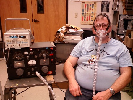
In the meantime, I had to see if 'patient admittance' is actually a measurable quantity. So, I got my trusty General Radio model 1608 Impedance Bridge, and my Sencore automatic inductor and capacitor analyzer. Below is a picture of my test setup. The results were, needless to say, inconclusive.......
Lions can and do snore....
Re: ResMed S9 coming soon?
Good'un, TimbaLionGuy!!!!
_________________
| Mask: Quattro™ FX Full Face CPAP Mask with Headgear |
| Additional Comments: PR SystemOne BPAP Auto w/Bi-Flex & Humidifier - EncorePro 2.2 Software - Contec CMS-50D+ Oximeter - Respironics EverFlo Q Concentrator |
Women are Angels. And when someone breaks our wings, we simply continue to fly.....on a broomstick. We are flexible like that.
My computer says I need to upgrade my brain to be compatible with its new software.
My computer says I need to upgrade my brain to be compatible with its new software.
-
DaveMunson
- Posts: 266
- Joined: Thu Jun 23, 2005 8:36 pm
Re: ResMed S9 coming soon?
You need wave guide and a magnetron (at least a klystron or travelling wave tube) to complete the circuit along with a larger flux capacitor load otherwise you will never dissipate 1.21 gigawatts of power. Unless you eat a burrito. If you eat a burrito, you will be able to dissipate, but the vent tube is plugged into the wrong hole.
_________________
| Mask | Humidifier | |||
 |  | |||
| Additional Comments: SleepyHead, ResScan 3.16, ClimatelLne Tube, Hosehuggie in Plaid (it's so cool) | ||||