Broken CPAP - Internal parts

General Discussion on any topic relating to CPAP and/or Sleep Apnea.
User avatar
Sludge
Posts: 953
Joined: Wed Dec 04, 2013 4:36 am

Re: Broken CPAP - Internal parts

Post by Sludge » Sat Dec 21, 2013 5:39 am

Sludge wrote:
cpaman wrote:Do you know what the baud rate settings and other settings to set the connection on com port?
This question is not clear to me. The board is from National Instruments, whose software LabView is the middleware to get from SysOne to Service Center Tools. LabView is configurable to suck up data as fast as the target will allow. If you're going to DIY an interface, it seems to me that what you need to know are the communication specifications of SysOne, right?
I mean, I can watch it at the shop (there is a properties tab once you hook up), but it's probably 9600 or 19,200, you only need one data small dump so it don't need to be 300 spagtillion bps, and what's next anyway? You have the error codes. The only other things you could do is clear the codes (and no reason to), set the clock (which you can't do without the software or maybe Jedimark could write something), upgrade firmware and/or run the OVP.

OK maybe that is a lot...
You Kids Have Fun!!

pbriggs
Posts: 173
Joined: Thu Aug 15, 2013 11:56 am

Re: Broken CPAP - Internal parts

Post by pbriggs » Sat Dec 21, 2013 6:51 am

most interesting - can you take a picture of the other side of the board also? On the board I see:
1. Upper right hand corner - that chip is just a voltage regulator made by TI 78M33c (http://www.ti.com/lit/ds/slvs059s/slvs059s.pdf) so nothing fancy here.
2. middle of the board is a chip Analog Devices ADUM5201, 2 channel isolator – dc-to-dc converter, digital (http://www.analog.com/en/interface-isol ... oduct.html) So, digital isolation so digital communication. Most interesting to me is that this is an automotive grade component - at least it is in an interface part and not the actual unit...
3. lower middle is another chip that is a TI MP227EC, RS232 communication chip (http://www.ti.com/lit/ds/slls715a/slls715a.pdf)

_________________
Mask: Mirage™ FX Nasal CPAP Mask with Headgear
Additional Comments: 14/10 with REM Sleep Behavior Disorder

pbriggs
Posts: 173
Joined: Thu Aug 15, 2013 11:56 am

Re: Broken CPAP - Internal parts

Post by pbriggs » Sat Dec 21, 2013 7:08 am

National instrument you mention why? Labview is a program we use at work to create software, it has many many uses - we use it to write software to control our equipment - which by the way is data acquisition equipment and test control logic. Kind of sounds like a basic CPAP machine - we use pressure sensors, flow, current, monitor RPM control temperatures, etc (automotive fuel systems is my end product where I work so we are always performing durability testing on them in gasoline for long term testing)... a really logic block based approach to writing software without having to know how to code... there are blocks of code available that you can drag and drop and connect to other blocks to get the "software" to behave how we need it to. I assume there is also code available that would allow you to flash a PROM to change a program, but never tried it before.

Do you actually use Labview in the repair of the machines, or did they create an executable from labview that allows you to change only what they want you to be able to do?

_________________
Mask: Mirage™ FX Nasal CPAP Mask with Headgear
Additional Comments: 14/10 with REM Sleep Behavior Disorder

pbriggs
Posts: 173
Joined: Thu Aug 15, 2013 11:56 am

Re: Broken CPAP - Internal parts

Post by pbriggs » Sat Dec 21, 2013 7:21 am

cpaman wrote:
My picture on the last posting didn't show up, it's the back side of the electronic board, with the pressure sensor on the top right of picture; 2 black box with snout on them. Here is the picture again.

Image
Looking at the various pictures - I see 2 sensors that are connected to the flow channel on the outlet of the pump. I assume the two sensors plug into the flow channel based on the first picture you had with the blower shown in the upper right of the blower unit you can see the interface points for the sensors.
So - my opinion - there are multiple things they can be. Somewhere in the system I assume there is a flow meter, or some other way to infer flow measurement and a pressure sensor. Just a guess is that the one with the two ports is measuring the pressure change, or a delta pressure sensor, where they are measuring the pressure on the inlet and outlet of an orifice. This is known as a differential pressure flow meter (http://www.omega.com/literature/transac ... -diff.html - a much larger example, but gives the theory on how they work). So, again my opinion, is that the one with the 2 ports is what they use to measure flow.

The other single port one is after what I assume is the orifice for the flow meter and is actually the one that measures the pressure.

Are there any markings on these parts at all?

_________________
Mask: Mirage™ FX Nasal CPAP Mask with Headgear
Additional Comments: 14/10 with REM Sleep Behavior Disorder

User avatar
Sludge
Posts: 953
Joined: Wed Dec 04, 2013 4:36 am

Re: Broken CPAP - Internal parts

Post by Sludge » Sat Dec 21, 2013 7:34 am

pbriggs wrote:Do you actually use Labview in the repair of the machines, or did they create an executable from labview that allows you to change only what they want you to be able to do?
It would appear to run in the background of Service Tools.

Mayhaps the easiest thing to do is rip off that sticker and get the Part#...
You Kids Have Fun!!

User avatar
SleepyCPAP
Posts: 333
Joined: Wed Dec 08, 2010 6:01 am

Re: Broken CPAP - Internal parts

Post by SleepyCPAP » Sat Dec 21, 2013 9:02 am

On an old 450 machine (which in this case had a different color board, blue rather than red) the two-port sensor was a Sensirion SDP700 series (which their online brochure lists as OEM series), and was SDP703-01, part number 1-100544-01. That was printed on the side of the sensor.

The 450 and 550 have the same schematics, so I'm guessing the part on cpaman's board has the same or a similar number. It is a "Thermal Anemometric Flow" sensor.

The machines lower than model 450 (the "bricks") don't have the two sensors, just one of them. The extra one for the data machines must be the small square pressure sensor with the one port and the eight pins, because the bricks are supposed to have the flow sensor.

Remember, I'm not a tech. I could be wrong.

And you all make me nervous about soldering and messing with essential medical equipment. Even if it runs after you get it back together, how are you going to test it to be sure the pressures, wave forms, and other data are right? It might not be so obvious as a wacky date code. Here is what the datasheets on the similar SDB600 say: "Standard wave soldering systems may be used for soldering SDP600 series sensors. Reflow soldering is not feasible and may damage the sensor. The sensor ports must be protected from solder splash and flux during soldering."
http://www.sensirion.com/en/products/di ... ad-center/
and if you want an idea of how these work, download the product flyer on that page.


--SleepyCPAP
edited once to correct spelling of "Sensirion". If I can get that wrong, assume I get other stuff wrong too. Sigh...
edited again to add the document reference on soldering SDB600.

_________________
Machine: AirCurve™ 10 VAuto BiLevel Machine with HumidAir™ Heated Humidifier
Mask: Bleep DreamPort CPAP Mask Solution
Additional Comments: Use OSCAR. Combine AlaxoStent with VAuto for perfect 0.0 AHI at PS 3.6 over 4cm EPAP
-- SleepyCPAP
Sleep study in 2010 (11cm CPAP). Pillows (Swift FX>TAP PAP >Bleep). PRS1 “Pro” 450/460 until recall, now Aircurve 10 VAuto. Tape mouth. Palatal Prolapse solved by AlaxoStent & VAuto EPAP 4cm, PS 3.6cm = 0.0 AHI

User avatar
Sludge
Posts: 953
Joined: Wed Dec 04, 2013 4:36 am

Re: Broken CPAP - Internal parts

Post by Sludge » Sat Dec 21, 2013 1:17 pm

SleepyCPAP wrote:Even if it runs after you get it back together, how are you going to test it to be sure the pressures, wave forms, and other data are right?
Zackly!

And more than simply being error-free, flow and pressure must be calibrated, as in the results presented in the "Firmware " thread:

Image
Image
You Kids Have Fun!!

cpaman
Posts: 11
Joined: Tue Feb 12, 2013 9:41 pm
Location: Tucson, AZ

Re: Broken CPAP - Internal parts

Post by cpaman » Sat Dec 21, 2013 5:43 pm

Changing the pressure sensor will most likely require re-calibration of the device. I'm curious if the program inside the chip would have to be re-adjust when the sensor is replace. Do we have any expert in this forum? Anybody know how to adjust the time on the device with the adapter? I got the date/time on my device messed up because I pulled the battery, and it lost it's internal clock.

pbriggs
Posts: 173
Joined: Thu Aug 15, 2013 11:56 am

Re: Broken CPAP - Internal parts

Post by pbriggs » Sat Dec 21, 2013 6:04 pm

that looks like a comprehensive list to tests - I especially like test #30 in relation to another thread where someone is having the plastic start to melt when the humidifier runs out of water - I would think the heater would shutoff. A plate temperature is not recorded in degrees - the unit is noted as A/D counts. Interesting

If I was playing with a machine I would be sure it was a spare one and not the one I count on to keep me alive

_________________
Mask: Mirage™ FX Nasal CPAP Mask with Headgear
Additional Comments: 14/10 with REM Sleep Behavior Disorder

User avatar
Sludge
Posts: 953
Joined: Wed Dec 04, 2013 4:36 am

Re: Broken CPAP - Internal parts

Post by Sludge » Sun Dec 22, 2013 4:37 am

cpaman wrote:Anybody know how to adjust the time on the device with the adapter?
Sure.

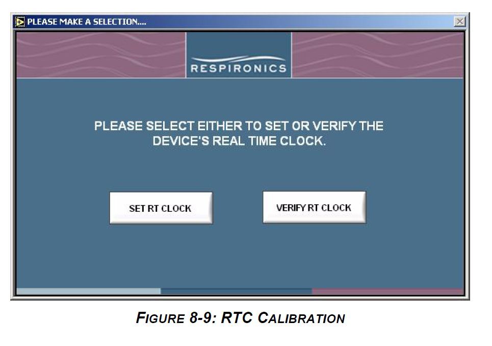
Just stick the aforementioned adapter on the back of the machine, run Service Center Tools, and select Real Time Clock Calibration:

Image

However, (and "IMHO") the LEAST of your worries is making sure your machine knows what time it is. The factory recommendations for the error codes previously mentioned say to replace the board, and while this discussion is certainly interesting for background on the hows and whys of the stuff that goes on behind the scenes, I think at some point (like this point), you just have to bite the bullet a get a new machine.
You Kids Have Fun!!

-SWS
Posts: 5301
Joined: Tue Jan 11, 2005 7:06 pm

Re: Broken CPAP - Internal parts

Post by -SWS » Sun Dec 22, 2013 4:03 pm

I think before giving up on the broken board, I'd try injecting short bursts of compressed air into the MAS flow sensor's two pressure ports, hoping to dislodge particulate matter.

I'd also look for hairline cracks right where the CPAP hose or humidifier fits onto the machine. That plastic coupling is susceptible to axial loading from tugging, and hence cracks are possible. Hairline cracks near the MAS flow sensor's feed tube might account for erratic/error-prone MAS airflow readings. Those can be resealed.

User avatar
Sludge
Posts: 953
Joined: Wed Dec 04, 2013 4:36 am

Re: Broken CPAP - Internal parts

Post by Sludge » Mon Dec 23, 2013 5:22 am

-SWS wrote:I think before giving up on the broken board, I'd try injecting short bursts of compressed air into the MAS flow sensor's two pressure ports, hoping to dislodge particulate matter.
Interestingly thought, -SWS!

From an earlier post, it appears that he had been using an ultrasonic humidifier and perhaps there are "hard water" deposits on there now.

I wonder how machines that have been subject to months/years of EO are performing now. While pressure/flow sensors might not be failing, at least becoming less accurate.
You Kids Have Fun!!

cpaman
Posts: 11
Joined: Tue Feb 12, 2013 9:41 pm
Location: Tucson, AZ

Re: Broken CPAP - Internal parts

Post by cpaman » Mon Dec 23, 2013 9:58 am

There was some hard water deposit in the CPAP when I was using it near the humidifier. I opened my CPAP box and clean the inside and the motor, though I didn't clean the pressure sensor. I'll try to clean the sensor at the next opportunity.

I got my CPAP running again. Usually every time the CPAP stop working in the morning, I would just unplug the wires, let it sit for few hours then it would run again. But the last time it stopped working, I had to let it sit for a about a couple of days. I don't understand why I would need to unplug the wires to be able to run the CPAP again.

From the error message in the previous posting, SleepyCPAP did say there were a lot of error on the flow sensor. I don't know if we could just change out the sensor, and if the chip would automatically re-adjust / re-calibrate the pressure.

-SWS
Posts: 5301
Joined: Tue Jan 11, 2005 7:06 pm

Re: Broken CPAP - Internal parts

Post by -SWS » Mon Dec 23, 2013 3:26 pm

cpaman wrote:There was some hard water deposit in the CPAP when I was using it near the humidifier. I opened my CPAP box and clean the inside and the motor, though I didn't clean the pressure sensor. I'll try to clean the sensor at the next opportunity.
Those Honeywell MAS flow sensors are supposed to be moisture tolerant regarding damage. But they're not tolerant of particulate matter, like the white residue from ultrasonic humidifiers. I'd try short bursts of compressed air first. If that didn't work, then I'd try a drop or three of vinegar & water before tossing the board or replacing the sensor.
Sludge wrote: I wonder how machines that have been subject to months/years of EO are performing now. While pressure/flow sensors might not be failing, at least becoming less accurate.
cpaman wrote: I don't know if we could just change out the sensor, and if the chip would automatically re-adjust / re-calibrate the pressure.
Dunno. But I'd be surprised if Respironics didn't write firmware code to compensate for ordinary sensor drift. Zero-sum inspiratory & expiratory flow reversals should make that a fairly easy task.

User avatar
Sludge
Posts: 953
Joined: Wed Dec 04, 2013 4:36 am

Re: Broken CPAP - Internal parts

Post by Sludge » Tue Dec 24, 2013 3:32 am

cpaman wrote:I don't know if we could just change out the sensor, and if the chip would automatically re-adjust / re-calibrate the pressure.
-SWS wrote:Dunno. But I'd be surprised if Respironics didn't write firmware code to compensate for ordinary sensor drift. Zero-sum inspiratory & expiratory flow reversals should make that a fairly easy task.
I would say it can't. In order to calibrate the flow and pressure sensors, it would have to send in a series of known flows and pressures (see above Service Report where this is done). Without additional flow and pressure sensors, it can never be sure what the flow and pressure is at any given time.

Further, "IMHO" it can't even zero. It would have to be sure there is no flow or pressure, and that scenario can never be assumed to be true in the field. The procedure would, out of necessity, have to be done at start up, and since plenty of people put the mask on first, then turn on the machine, there is never a true zero state.

That said, if there were such a routine, then there should be an indicator if it fails, and if we look at the available Error Codes for flow and pressure:

Pressure Sensor Errors

E-70 ERR_PRESSURE_SENSOR_ABSENT
E-72 ERR_PSENS_UNABLE_TO_OBTAIN_BUS
E-73 ERR_SENSOR_PRESS_OFFSET_STOP

Flow Sensor Errors

E-80 ERR_UNABLE_TO_INIT_FLOW_SENSOR
E-81 ERR__FLOW_SENSOR_TABLE
E-82 ERR_FLOW_SENSOR_OFFSET
E-83 ERR_FSENS_UNABLE_TO_OBTAIN_BUS
E-84 ERR_FLOW_SENSOR_STOP
E-85 ERR_FLOW_SENSOR_OCCLUDED
E-86 ERR_FLOW_SENSOR_ABSENT
E-87 ERR_FLOW_SENSOR_BUS

there are those OFFSET things, but it cannot necessarily be assumed that where you're offsetting from is actually zero.

That said2, in a review of Respironics technology, it seems that Flow Offset only comes into play when the patient is actually "doing something":
"FlowOffset" corresponds to a final value of patient flow during inspiration responsive to the final value being positive, otherwise FlowOffset is set to zero.
That said3, that certainly does not mean that once one exceeds zero flow and/or pressure, that those delivered parameters are accurate.
You Kids Have Fun!!